Installation Instructions
Before you begin
The following instructions describe the recommended installation procedure for the ResTrack Lite Controller and associated hardware components.
Before commencing installation, ensure all required components are available and that the installation site has been prepared in accordance with local safety requirements.
Pre-installation Guidelines
Correct installation of the ResTrack Lite Controller is essential to ensure safe operation and reliable system performance. Before commencing installation, confirm that the site has been prepared in accordance with local safety requirements and that all required components are available.
- Complete all required hazard identification, risk assessment, monitoring, and control measures in accordance with site procedures.
- Do not install new components or modify an existing ResTrack Lite Controller installation without prior assessment and approval from Banlaw.
- The ResTrack Lite Controller is not designed for high-vibration environments, such as mobile vehicle applications.
- Inspect all hardware before installation. Do not install damaged or faulty components.
- Ensure all electrical devices connected to the controller are compatible with the ResTrack Lite system.
- Only install components that have been approved for use with the ResTrack Lite Controller.
- Electrical installation and wiring must only be carried out by suitably qualified personnel.
- Ensure all threaded pipe connections use matching thread types. Clean all threads before assembly and apply a suitable thread sealant or thread tape where required.
- Install the ResTrack Lite Controller out of direct sunlight wherever possible to maximise reliability and extend the service life of the enclosure.
- Ensure all mounting hardware is suitable for the installation and correctly matches the controller mounting points.
- Tighten all fasteners using the appropriate tools and recommended torque values.
- The controller enclosure is supplied with an IP66 environmental rating. Do not drill or modify the enclosure, as this may compromise its ingress protection.
- Confirm that all mechanical and electrical isolation procedures have been completed before commencing installation.
Generic ResTrack Lite System Installation Procedure
The following procedure outlines a typical ResTrack Lite installation. Depending on the installation environment and selected hardware, additional commissioning or site-specific requirements may be necessary.
- The ResTrack Lite Controller must not be installed within a hazardous area.
- All electrical connections must be completed by a qualified electrician.
- Air eliminators, filters, and strainers should be installed in accordance with the manufacturer's installation instructions.
- Complete all required hazard identification, risk assessment, and site isolation procedures.
- Unpack the ResTrack Lite Controller and verify that all required components are present and free from damage.
- Determine suitable mounting locations for the controller and all associated hardware.
- Mount the controller in a location where it is protected from accidental damage, excessive vibration, and environmental exposure.
- Confirm that a suitable power source is available for the controller.
- Install a Y-Strainer or suitable inline filter upstream of the flow meter to protect the flow meter from contamination and debris.
- Install the pipework and dispensing components in the order shown below.
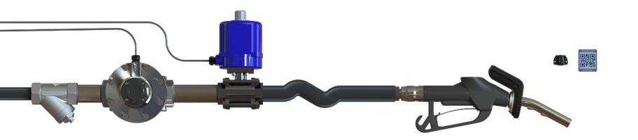
Y Strainer
Flow
Meter
Actuated Valve
Dispensing Nozzle
Generic ResTrack Lite LV Refuelling Arm
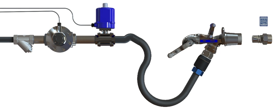
Y Strainer
Flow
Meter
Actuated Valve
Dispensing Nozzle
Generic ResTrack Lite HV Refuelling Arm
BRTLLS01A Level Sensor Installation Procedure
The following procedure describes how to assemble and install the Banlaw Level Sensor for use with the ResTrack Lite Controller.
Correct installation is important to ensure accurate tank level measurement and reliable long-term operation.
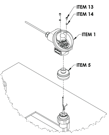
Exploded View and Bill of Materials
The exploded view below identifies each component included in the Banlaw Level Sensor assembly. The accompanying Bill of Materials (BOM) provides the item numbers referenced throughout the installation procedure.
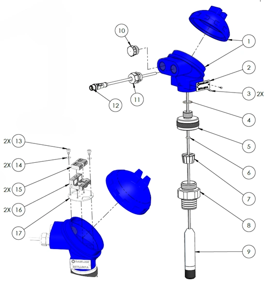
BRTLLS01A Exploded View
Package Contents
Each Level Sensor kit includes a pre-assembled Level Sensor Head with process connection and the pressure transducer assembly.
Before beginning installation, verify that all components are present and free from damage.
The following procedure explains how to assemble the level sensor and install it into a compatible storage tank.
The level sensor measures hydrostatic pressure at the bottom of the storage tank and converts this measurement into a percentage of the tank's capacity.
Because the measurement is pressure-based, the sensor can be installed in both regular and irregular shaped tanks, including rectangular and cylindrical tanks.
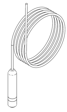
The supplied level sensor is suitable for tanks with a maximum depth of 5 metres, which is determined by the length of the supplied pressure transducer cable.
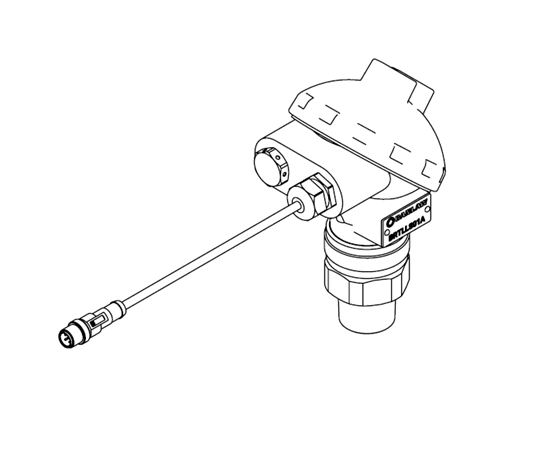
Level Sensor Head
Level Sensor
Level Sensor Installation Procedure
Follow the procedure below to assemble and install the level sensor. Images are provided throughout the installation process to assist with each step.
Level Sensor Head
Level Sensor
Level Sensor Installation Procedure
Follow the procedure below to assemble and install the level sensor. Images are provided throughout the installation process to assist with each step.
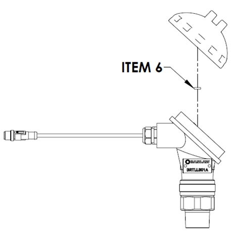
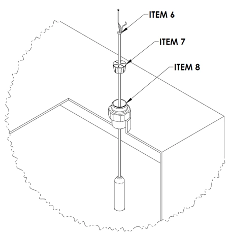
- Disassemble the Level Sensor Head and remove the retaining O-ring (Item 6).
-
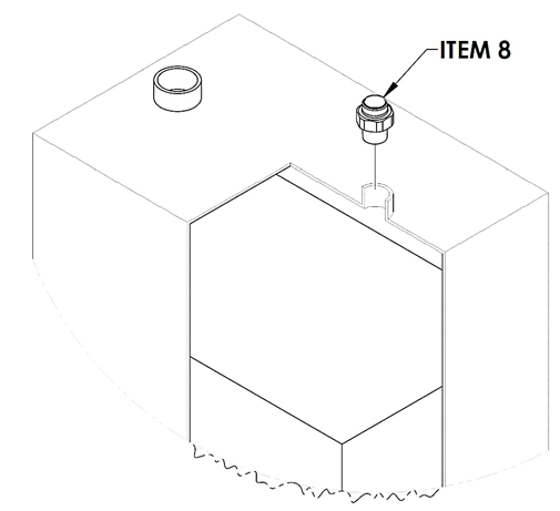
Apply a suitable thread sealant or thread tape to the 1" BSPT (M) thread on Item 8.
-
Install Item 8 into the designated tank mounting point.
Note: Tighten using the Turns From Finger Tight (TFFT) method, applying approximately 1.5–2.5 turns beyond finger tight.
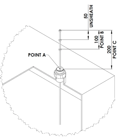
- Lower the pressure transducer (Item 9) through Item 8 until it rests on the bottom of the storage tank.

-
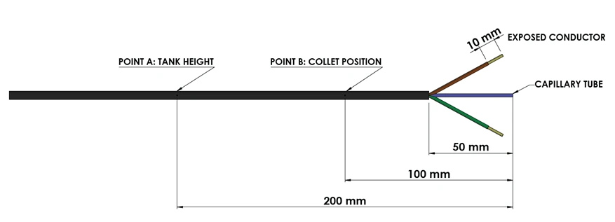
Mark the pressure transducer cable at Point A where the pressure transducer reaches the bottom of the tank.
-
Measure 200 mm from Point A and mark this position as Point C.
-
Using approved tools, cut the pressure transducer cable at Point C.
-
Remove approximately 50 mm of the outer cable sheath to expose the internal conductors.
Note: Take care not to damage the capillary tube during this process.
-
Strip approximately 10 mm of insulation from each conductor.
-
Measure 100 mm from the stripped conductors and mark this position as Point B.
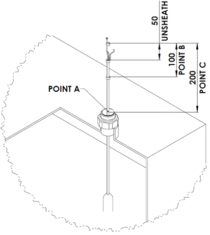 11. Slide the following components approximately 200 mm onto the pressure transducer cable in the order shown:
- Collet (Item 7)
- Retaining O-ring (Item 6)
-
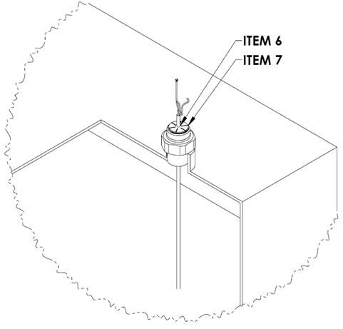
Position the collet (Item 7) at Point B and secure it in place.
Note: At this stage, the pressure transducer should be resting on the bottom of the storage tank.
-
Slide the retaining O-ring (Item 6) down onto the collet (Item 7).
-
Hand tighten Item 5 to secure the level sensor within the tank.
Note: No tools are required. Tighten the Adaptor, 5 mm Gland Body by hand only.
-
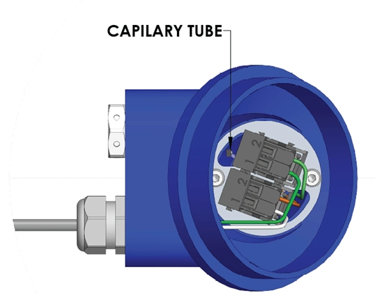
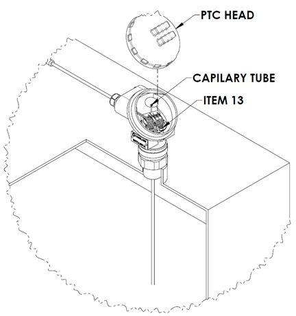
Remove both M4 × 6 screws (Item 13) from the Level Sensor Head (Item 1) to allow the cable to be installed.
-
Feed the sensor cable into the Level Sensor Head (Item 1) and hand tighten the assembly.
Note: Tighten the PTC Head by hand only.
- Route the capillary tube through the opening shown in the diagram below.
-
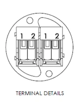
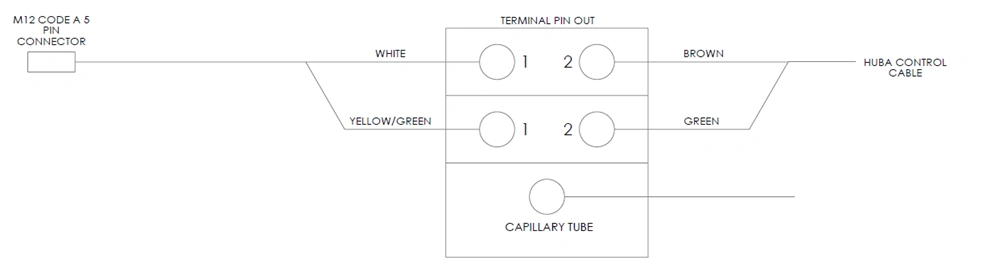
Terminate the level sensor conductors into Position 2 of the terminal connector (Item 15) as shown in the wiring diagram below.
Important: Do not terminate the white wire from the pressure transducer.
Feed unsheathed
wires through here
Feed capillary
tube through here
-
Reinstall both M4 × 6 screws (Item 13).
-
Refit the PTC Head cover to complete the level sensor assembly.
The level sensor has now been installed and is ready to be connected to the ResTrack Lite Controller.
Before commissioning the system, verify that:
- All electrical connections are secure.
- The level sensor cable and capillary tube have not been damaged.
- The Level Sensor Head is fully assembled.
- All cable glands have been tightened correctly.