Controller Kits And Components
The ResTrack Lite Controller is designed to integrate with the hardware required to monitor, control, and record fuel dispensing operations. Banlaw offers a range of compatible components that have been designed and tested for use with the ResTrack Lite system.
Where suitable equipment is already installed, compatible third-party hardware may also be used provided it meets the required electrical and interface specifications. This page provides an overview of the available ResTrack Lite components, along with their specifications and compatibility requirements.
BRTLC01A-* Controller Kit
The ResTrack Lite Controller Kit contains the core hardware required for a standard installation. Each kit includes the controller, a power connection option appropriate for the selected region, and vehicle QR tags used for vehicle identification during fuel dispensing.
The controller forms the centre of the ResTrack Lite system, managing connected hardware and communicating with the ResTrack Lite platform.
- 1 x BRTLC01A - Banlaw ResTrack Lite Controller
- 1 x Power Supply or L coded connector
- 20 x BRTLC016 – Vehicle QR Tags
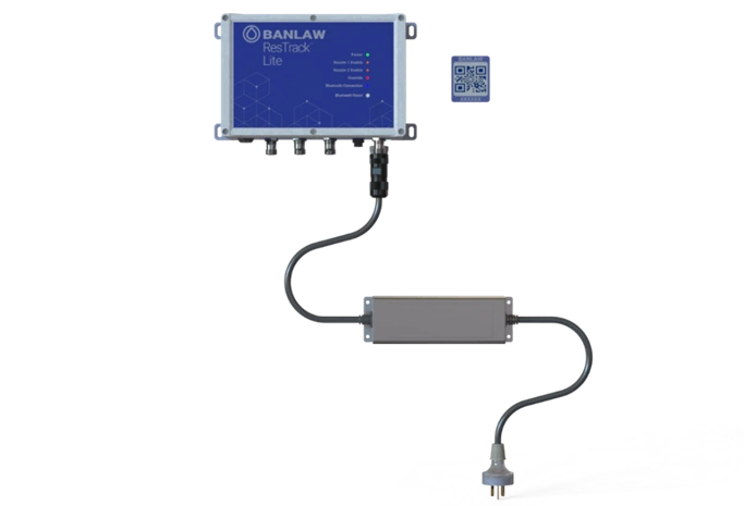
BRTLC01A
RTL Controller
BRTLC016
QR Code
BRTLPS**A
Power Supply
Standard Controller Kit
| Part Number | Description | Region |
|---|---|---|
| BRTLC01A-1 | Controller Assembly, ResTrack Lite, Code L Connector | ALL |
| BRTLC01A-2 | Controller Assembly, ResTrack Lite, Type I Power Supply | AU |
| BRTLC01A-3 | Controller Assembly, ResTrack Lite, Type B Power Supply | US/PHL |
| BRTLC01A-4 | Controller Assembly, ResTrack Lite, Type F Power Supply | EU/IDN |
ResTrack Lite Controller Kit part number BRTLC01A-1 should only be chosen if a reliable 12-24VDC power supply is available
BRTLPS**A - Power Supply
The ResTrack Lite Controller can be powered using either a Banlaw supplied power supply or a field-wireable connector where a regulated DC supply is already available. The appropriate option depends on the installation environment and available power infrastructure.
The Banlaw power supply is designed for reliable operation across a wide range of industrial environments and provides the regulated power required by the controller.
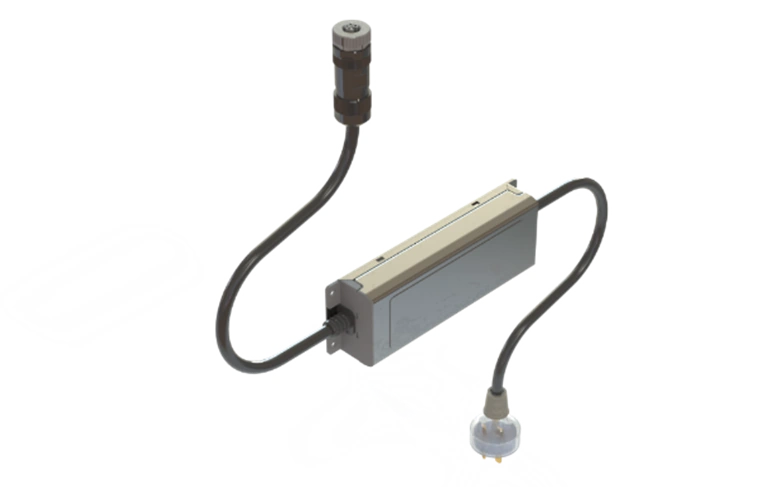
BRTLPS01A – Power Supply Assembly, Type I
Banlaw supplied Power Supply Specifications as follows:
| Parameter | Value |
|---|---|
| Operating Temperature | -40°C (-40°F) to 80°C (176°F) |
| Input Voltage Range | 100-305 VAC |
| Output Voltage | 24VDC |
| Rated Power | 96W (4A @ 24VDC) |
| IP Rating | IP67 |
Field Wireable L Coded Plug (Banlaw P/N 001993) should only be chosen if an existing 12-24VDC @ 4A power source is available.
Field Wireable L-Coded Connector
The Field Wireable L-Coded Connector provides a convenient method of connecting the ResTrack Lite Controller to an existing regulated 12–24 VDC power source. This option is intended for installations where a suitable DC power supply has already been installed.
The following pinout and assembly procedure describe the recommended wiring configuration for the connector.
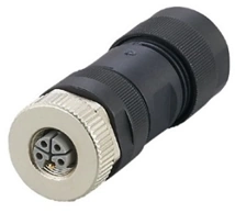
Field Wireable L Coded Connector (Banlaw Part No: 001993)
Pinout diagram
| Pinout Diagram | Pin NO. | Description |
|---|---|---|
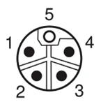 | 1 | +V |
| 3 | 0V | |
| 2, 4, 5 | Not in use |
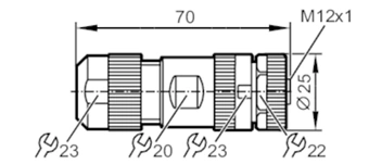
L Coded Connector Overall Dimensions & Tools Required
Input Power Specifications | |
| Input Voltage Range | Regulated 12-24 VDC |
| Rated Power | 40mA at 12VDC / 20mA at 24VDC |
Cable Specifications | |
| Wire gauge | Regulated 12-24 VDC |
| Cable sheath diameter | 40mA at 12VDC / 20mA at 24VDC |
General Connector Assembly Procedure
Follow the steps below to correctly terminate and assemble the Field Wireable L-Coded Connector.
- Strip the wires to expose 8mm of conductor.
- Place a bootlace ferrule on each core.
- Unscrew the compression gland and the body shell from the connector.
- Insert the +V wire into terminal 1 and tighten the screw.
- Insert the 0V wire into terminal 3 and tighten the screw.
- Screw the connector body into the connector.
- Tighten the compression gland.
- Tighten the body shell to ensure a secure fit.
Voltage Stabilisers
A stable power supply is essential for reliable controller operation. Where a regulated DC supply is unavailable, a voltage stabiliser can be installed to provide a consistent 12–24 VDC output and protect the controller from fluctuations in the incoming supply.
Banlaw recommends using a suitable voltage stabiliser where vehicle or site power is subject to variation.
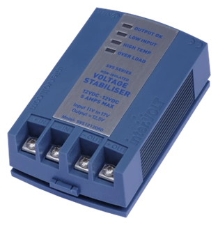
Voltage Stabiliser, 12V-12V DC, 000769
| Input Voltage | Part Number | Description |
|---|---|---|
| 11-17V | 000769 | Voltage Stabiliser, Intervolt, 12V-12V DC |
| 22-33V | 001932 | Voltage Stabiliser, Intervolt, 24V-24V DC |
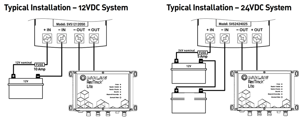
Typical 12VDC or 24VDC Voltage Stabiliser Installation System
Please refer to manufacturer's installation & operation manual prior to assembly:
https://www.intervolt.com/wp-content/uploads/2015/07/interVOLT-SVS-Manual.pdf
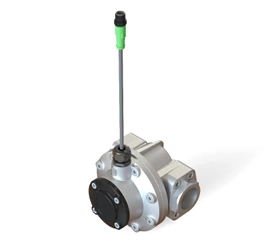
BRTLAV**A - Ball Valves
The ResTrack Lite Controller supports up to two actuated ball valves or other compatible flow control devices. These valves control the flow of fuel during dispensing, allowing the controller to authorise or prevent fuel delivery based on user permissions and transaction status.
The controller provides a ground-switched (low-side) control output, enabling compatible actuated ball valves to be integrated into a wide range of fuel dispensing systems.
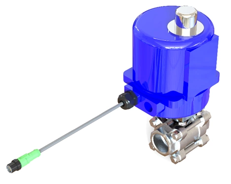
Actuated Ball Valve
In the event of a power failure this Actuator Valve will not fail closed. If a fail to close system is required, an alternate valve will need to be selected. Contact Banlaw for assistance in this regard.
Banlaw assembled Actuated Ball Valve electrical specifications as follows:
| Part Number | Description | Process Connection |
|---|---|---|
| BRTLAV01A | Valve, Ball, Actuated, 1” BSPT (F), OM-1, M12 Code A 5m, 24VDC | 1” BSP (F) |
| BRTLAV02A | Valve, Ball, Actuated, 1.5” BSPT (F), OM-1, M12 Code A 5m, 24VDC | 1.5” BSP (F) |
| BRTLAV03A | Valve, Ball, Actuated, 2” BSPT (F), OM-1, M12 Code A 5m, 24VDC | 2” BSP (F) |
| BRTLAV04A | Valve, Ball, Actuated, 1” NPT (F), OM-1, M12 Code A 5m, 24VDC | 1” NPT (F) |
| BRTLAV05A | Valve, Ball, Actuated, 1.5” NPT (F), OM-1, M12 Code A 5m, 24VDC | 1.5” NPT (F) |
| BRTLAV06A | Valve, Ball, Actuated, 2” NPT (F), OM-1, M12 Code A 5m, 24VDC | 2” NPT (F) |
Alternate Ball Valve Actuator Pinout Diagram
Existing 24 VDC actuated ball valves can be connected to the ResTrack Lite Controller provided they meet the required electrical specifications.
Refer to the pinout diagram below for the recommended wiring configuration when integrating a compatible third-party actuator.
| M12 Connector Pinout Diagram | Pin NO. | Description |
|---|---|---|
 | ||
| 1 | +V | |
| 2 | OPEN | |
| 3 | 0V | |
| 4 | CLOSE | |
| 5 | Unused |
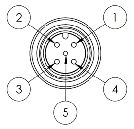
Generic Pump Start Pinout Diagram
The ResTrack Lite Controller can also be configured to provide a pump enable signal instead of controlling an actuated ball valve. This allows the controller to enable or disable external pumping equipment as part of the fuel dispensing process.
Depending on the application, the control output can be configured as either 24 VDC or 0 V switching. Refer to the pinout diagram below for the recommended wiring configuration.
| M12 Connector Pinout Diagram | Pin NO. | Description |
|---|---|---|
| ||
| 1 | +V | |
| 2 | OPEN | |
| 3 | 0V | |
| 4 | UNUSED | |
| 5 | UNUSED |
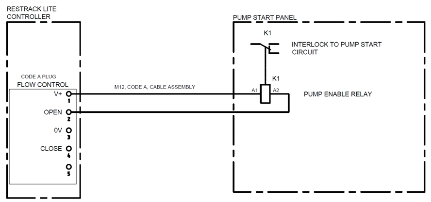
Generic Pump Start Electrical Diagram
BRTFLM**A - Flow Meters
Flow Meter
Flow meters measure the volume of fuel dispensed during each transaction. The ResTrack Lite Controller supports up to two Hall Effect flow meters, providing accurate fuel measurement for both single and dual-nozzle installations.
Refer to the flow meter manufacturer's installation guidelines for mechanical installation and commissioning requirements.
Banlaw Flow Meter Specifications
The following specifications apply to Banlaw supplied Hall Effect flow meters.
| Power Input | 12 - 24 VDC |
| Signals | 24V 0V Signal |
| Switch Type | Hall Effect |
The range of Flow Meters offered by Banlaw:
| Part Number | Description | Process Connection | Max Pressure | Max Flow rate |
|---|---|---|---|---|
| BRTLFM01A | Flowmeter, Hall Effect, 1” BSPP (F), M12 Code A | 1” BSPP (F) | 68 bar (1000 psi) | 150 lpm (40 gpm) |
| BRTLFM02A | Flowmeter, Hall Effect, 1.5” BSPP (F), M12 Code A | 1.5” BSPP (F) | 30 bar (440 psi) | 250 lpm (66 gpm) |
| BRTLFM03A | Flowmeter, Hall Effect, 2” BSPP (F), M12 Code A | 2” BSPP (F) | 20 bar (300 psi) | 450 lpm (120 gpm) |
| BRTLFM04A | Flowmeter, Hall Effect, 1” NPT (F), M12 Code A | 1” NPT (F) | 68 bar (1000 psi) | 150 lpm (40 gpm) |
| BRTLFM05A | Flowmeter, Hall Effect, 1.5” NPT (F), M12 Code A | 1.5” NPT (F) | 30 bar (440 psi) | 250 lpm (66 gpm) |
| BRTLFM06A | Flowmeter, Hall Effect, 2” NPT (F), M12 Code A | 2” NPT (F) | 20 bar (300 psi) | 450 lpm (120 gpm) |
It is recommended that a filter or 100 mesh (150 micron) Y-Strainer is installed upstream of the flow meter to prevent debris from entering the measuring chamber.
ResTrack Lite supports Hall Effect flow meters only. Other signal types are not compatible with the controller.
Generic Hall Effect Sensor Pinout Diagram
Existing Hall Effect flow meters may be connected to the ResTrack Lite Controller provided they meet the supported electrical and signal requirements listed below.
Compatible flow meters must provide:
- A 3-wire Hall Effect output
- A 24 VDC power supply
Refer to the following pinout diagram for the recommended wiring configuration.
| M12 Connector Pinout Diagram | Pin NO. | Description |
|---|---|---|
| ||
| 1 | +V | |
| 2 | UNUSED | |
| 3 | 0V | |
| 4 | UNUSED | |
| 5 | FLOW SIGNAL |
Y-Strainer
A Y-Strainer helps protect the flow meter by preventing debris from entering the measuring chamber. Installing a 100 mesh (150 micron) strainer upstream of the flow meter improves measurement accuracy and can extend the service life of the flow meter.
Banlaw recommends installing a Y-Strainer in all fuel dispensing installations where contamination may be present.
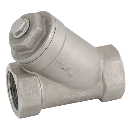
Y-Strainer
Below are the Y-Strainer options and part numbers offered by Banlaw:
| Part Number | Description | Process Connection | Mesh Size |
|---|---|---|---|
| 001999 | Y Strainer, 1" BSPT, SS, 150um | 1” BSPP (F) | 100 mesh / 150um |
| 001998 | Y Strainer, 1-1/2" BSPT, SS, 150um | 1.5” BSPP (F) | 100 mesh / 150um |
| 001997 | Y Strainer, 2" BSPT, SS, 150um | 2” BSPP (F) | 100 mesh / 150um |
| 001996 | Y Strainer, 1" NPT, SS, 150um | 1” NPT (F) | 100 mesh / 150um |
| 001995 | Y Strainer, 1-1/2" NPT, SS, 150um | 1.5” NPT (F) | 100 mesh / 150um |
| 001994 | Y Strainer, 2" NPT, SS, 150um | 2” NPT (F) | 100 mesh / 150um |
BRTLLS01A Level Sensor
Tank level sensors provide real-time visibility of the fuel stored within a tank. The ResTrack Lite Controller supports a single 4–20 mA level sensor, allowing fuel inventory to be monitored and displayed throughout the ResTrack Lite platform.
Tank level information can also be used to support inventory management and fuel reporting.
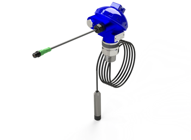
Level Sensor
RTL Controller only supports 1 fuel tank/level instrument. If more than 1 tank or fluid type is being used, a second controller will be required.
Refer to assembly procedure for the termination diagram, BRTLLS01A Level Sensor Installation Procedure.
Banlaw Level Sensor Specifications
The following specifications apply to the Banlaw supplied level sensor.
| Parameter | Value |
|---|---|
| Power Input | 12 - 24 VDC |
| Signals | 24V, 0V |
| Feedback Type | 4-20 mA signal |
| Process Connection | 1” BSPT (M) |
| Max. Depth | 5 m / 16.4 ft |
BRTSFL101 Banlaw SecureFill Auto ID
SecureFill Auto ID provides automatic vehicle identification during fuel dispensing, eliminating the need for manual vehicle selection. Each vehicle is assigned a unique identification tag, allowing ResTrack Lite to authorise fuel dispensing and accurately associate every transaction with the correct vehicle.
The SecureFill Wireless Gateway acts as the communication hub between the nozzle equipment and the ResTrack Lite Controller. It supports both SecureFill Splash Fill and Dry Break systems, enabling wireless communication between the identification equipment and the controller.
The SecureFill Wireless Gateway communicates exclusively with Banlaw SecureFill (HID identiTAG) equipment and is not compatible with Orpak Wireless components.
SecureFill Auto ID provides the highest level of vehicle identification available within the ResTrack Lite platform. Automatic identification helps ensure that fuel can only be dispensed to authorised vehicles while eliminating manual vehicle selection during transactions.
A single BRTSFL101 SecureFill Wireless Gateway can support up to two dispensing nozzles, making it suitable for both single and dual-nozzle installations.
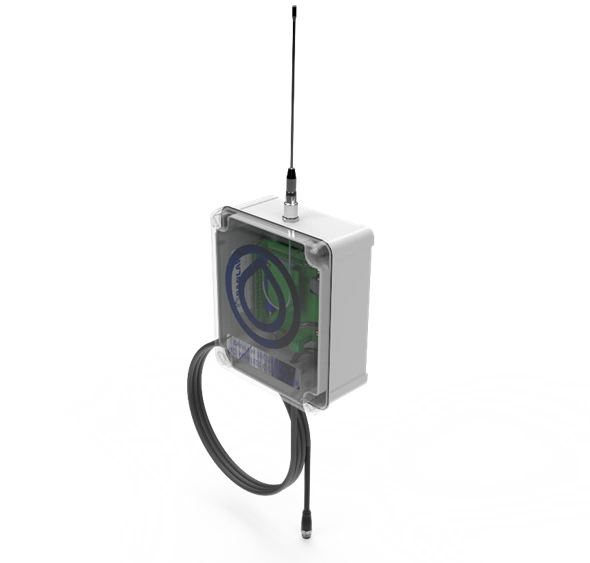
BRTSFL101 ResTrack Lite Auto ID Gateway
SecureFill Wireless Gateway Specifications
The following specifications apply to the Banlaw SecureFill Wireless Gateway.
| Technical Specification | SI Units | Imperial Units |
|---|---|---|
| Operating Temperature | -25°C < T < +60°C | -13°F < T < 140°F |
| Unit Dry Weight | 741 g | 1.63 lbs. |
| Range | 40 m | 131.2 ft |
| Antenna Frequency | 433.92 MHz | |
| IP Rating | IP67 |
Banlaw SecureFill Auto ID System
SecureFill Auto ID provides an automatic vehicle recognition. This form of identification is the highest security that ResTrack Lite offers. Contact a Banlaw representative if you are unsure about what type of solution should be implemented for your use case.
A single base station BRTSFL101 can support up to 2 nozzles of any type.
High Flow Dry Break Wireless Auto ID System
The High Flow Dry Break Wireless Auto ID System is designed for heavy-duty fuel dispensing applications where secure vehicle identification is required.
The wireless swivel combines the functionality of a conventional swivel with an integrated identification interface, allowing authorised vehicles to be recognised automatically when connected to a compatible Banlaw Dry Break receiver. This provides secure contact-based identification while maintaining a streamlined dispensing process.
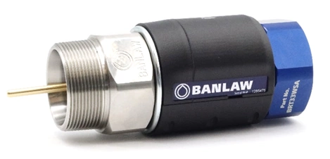
BRT3*WSA SecureFill Dry Break Wireless Swivel
Low Flow Splash Fill Wireless Auto ID System
The Low Flow Splash Fill Wireless Auto ID System provides automatic vehicle identification for splash fill dispensing applications.
Short-range RFID technology is used to transmit a unique vehicle identifier from the nozzle to the SecureFill Wireless Gateway, allowing ResTrack Lite to authorise fuel dispensing and automatically associate each transaction with the correct vehicle.
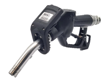
BRTSFL200 SecureFill LV Nozzle
Connection Cable, 5m, M12, A Code, Straight (M) Straight (F)
An M12 A-Coded Extension Cable is available where the standard pre-terminated cable length is insufficient for the installation.
The extension cable can be used with supported process connections throughout the ResTrack Lite system, excluding the SecureFill Wireless Gateway.
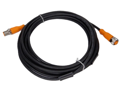
001992 A Coded Extension Cable
Extension Cable Specifications
The following specifications apply to the Banlaw M12 A-Coded Extension Cable.
| Part Number | Description | Process Connection |
|---|---|---|
| 001992 | Connection Cable, 5m, M12, A Code, Straight (M) Straight (F) | M12 A Coded Connector |
Third-Party Hardware Compatibility
ResTrack Lite has been designed to integrate with a range of compatible third-party hardware, allowing existing site equipment to be retained where it meets the required electrical and communication specifications.
Although Banlaw recommends using Banlaw supplied hardware, compatible third-party components may also be integrated with the ResTrack Lite Controller. The examples below represent commonly used hardware that meets the controller interface requirements.
Compatibility should always be verified against the manufacturer's specifications before installation.
Flow Meters
| Manufacturer | Example Products |
|---|---|
| GPI | TM Series Hall-effect flow meters |
| Macnaught | MX Series pulse-output flow meters |
| FLOMEC | OM Series pulse-output flow meters |
| Great Plains Industries | Industrial pulse-output flow meters |
These flow meters typically provide Hall Effect pulse outputs compatible with the ResTrack Lite Controller. When commissioning a third-party flow meter, the correct K-factor should be configured within ResTrack Lite to ensure accurate volume measurement.
Actuated Ball Valves
| Manufacturer | Example Products |
|---|---|
| OMAL | 12 VDC / 24 VDC actuated ball valves |
| Belimo | 12 VDC / 24 VDC valve actuators |
| Valpes | 12 VDC / 24 VDC valve actuators |
| J+J Electric | 12 VDC / 24 VDC valve actuators |
Valve Requirements
Valve Requirements
Third-party actuated ball valves must be compatible with the ResTrack Lite controller outputs and operate from the same supply voltage as the controller.
- 12 VDC input power requires a 12 VDC ball valve or solenoid
- 24 VDC input power requires a 24 VDC ball valve or solenoid
- The controller provides a ground-switched (low-side) control signal.
- Refer to the controller pinout diagrams for the recommended wiring configuration.
- The controller output is protected by a 4 A fuse.
| Supply Voltage | Maximum Current | Maximum Power |
|---|---|---|
| 12 VDC | 4 A | 48 W |
| 24 VDC | 4 A | 96 W |
The combined current draw of connected valve actuators should not exceed the controller output rating shown above.
Level Sensors
| Manufacturer | Example Products |
|---|---|
| VEGA | 4–20 mA hydrostatic level transmitters |
| Endress+Hauser | Deltapilot Series |
| WIKA | LH-20 Series |
| Gems Sensors | 4–20 mA tank level sensors |
Level Sensor Requirements
Third-party level sensors must provide a standard 4–20 mA analogue output and operate from a 12 VDC supply. Compatible sensors can be connected directly to the ResTrack Lite Controller for fuel tank level monitoring.
Known Incompatibilities
The following third-party equipment is not compatible with the ResTrack Lite Wireless Identification Gateway:
| Equipment | Compatibility |
|---|---|
| Orpak Wireless Auto-ID Components | Not compatible with the ResTrack Lite Wireless Identification Gateway |
For automatic vehicle identification, the ResTrack Lite platform communicates exclusively with Banlaw SecureFill® and HID identiTAG® equipment.
Recommended Third-Party Integration Configuration
The following configuration represents a typical third-party hardware installation using the ResTrack Lite Controller alongside compatible non-Banlaw components:
| Component | Recommendation |
|---|---|
| Controller | ResTrack Lite Controller (required) |
| Ball Valve | Third-party 12 VDC or 24 VDC actuated valve matching system voltage |
| Flow Meter | Third-party Hall-effect pulse-output flow meter |
| Level Sensor | Third-party 4–20 mA level sensor (12 VDC supply) |
| Power Supply | 12 VDC or 24 VDC power supply sized for the installation |